Assembling the Facedancer21
- facedancer
- goodfet
- usb
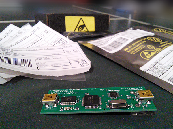
The Facedancer is a board to fuzz and emulate/prototype USB devices with host side python, PyUSB. Here is the official Facedancer21 page. It was masterminded by Travis Goodspeed and Sergey Bratus. The Facedancer21 is the 24th revision of the pcb.
The Facedancer is not really available pre-assembled for cheap so you will have to build your own. You can buy a fully assembled version from this site but you don't get any SMD soldering practice and it costs about double.
If you already have a board and need some help flashing it and emulating your first device, follow this guide.
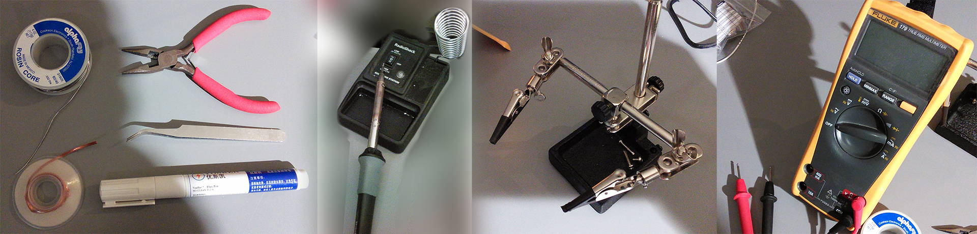
Tools:
- Soldering Iron
- Spool of Solder
- Flux (I used a flux pen)
- Tweezers
- Spool of desoldering Wick or Braid
- Multimeter for testing
- Helping hands
- Magnifying glass or something of the sorts
Parts:
You can order the Facedancer PCB by following the instructions on this page
I ordered double of the jelly-bean parts (resistors, capacitors, LEDs) in case I messed up soldering or lost one. All of the parts will run you about $35 from Digikey.
Once you have received all of your parts, make sure they sent you the right parts. Visually inspect and match them to the images on Digikey. Digikey made a pick-error and sent me the wrong part. I got some 1k resistors instead of the 0.1uF caps. I didn't realize this when soldering them and when I plugged in the board it caused my PC to Blue Screen(BSoD). Luckily the good people in the #goodfet IRC channel were able to spot that I had resistors where the caps should be.
| Part (link to Digikey) | Package | Quantity |
|---|---|---|
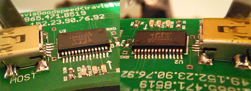
| FT232RL | SSOP28 | 1 |
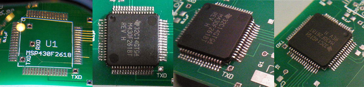
| MSP430F2618TPM | QFP64 | 1 |
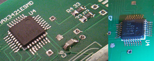
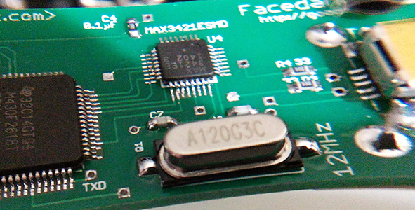
| MAX3421E | TQFP32 | 1 |
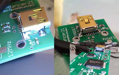
| USB Mini female | 2 | |
| USB Type A female | 1 | |
| 12 Mhz Crystal | HC49/US | 1 |
| 27pF capacitors | 0603 | 2 |
| 1uF capacitors | 0603 | 2 |
| 0.1uF Decoupling Capacitors | 0603 | 3 |
| 0603 LEDs | 0603 | 3 |
| 330ohm Resistors | 0603 | 2 |
| 33ohm Resistors | 0603 | 2 |
Assembly:
Here are a few SMD soldering tutorials to watch before you get started:
If you have any random boards and parts, practice with those a bit before starting.
I used a couple techniques to accomplish the job. Both of them are shown and explained in the video tutorials I mentioned above:
- Tack and place: Flux the pads. Put a bit of solder onto on of the pads. Use your tweezers to place the part and reflow the solder you just put on. Slide the part into place and remove the iron. Solder the rest of the pins/pads.
- Drag soldering: Flux the pads. Tack down a pin on multiple sides of the chip. Flux again. Add a little bit of solder to the first couple of pins. Now move your iron back and forth across the side until the solder flows to all the pins. You will have to make multiple passes. If you can't get solder to flow all the way down the to last pins on the side just add a bit to that side and repeat. Repeat for all sides. Check for solder bridges with your magnifying utility and use the desoldering wick/braid to clean them up.
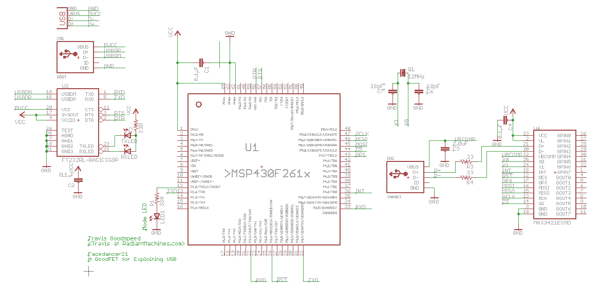
Use the lowest temperature setting with your soldering iron that will still melt the solder. This will minimize lifting of pads, etc. It is extremely easy to lift the pads where there is a no-connect (NC). Most of the pins on the MSP430 are left unconnected so if you accidentally lift a pad, check the schematic (below) to see if it is used. Just clean up the bridges.
Steps:
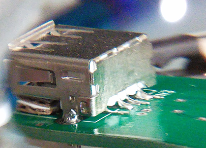
- Start with the QFP64 MSP430 chip.
This is probably the hardest part of this build. A 64 pin 0.5mm pitch chip with very few pins actually connected to something else. You can see that a couple of pads lifted in the image, but fortunately only on unused pins (NC, not connected to anything).
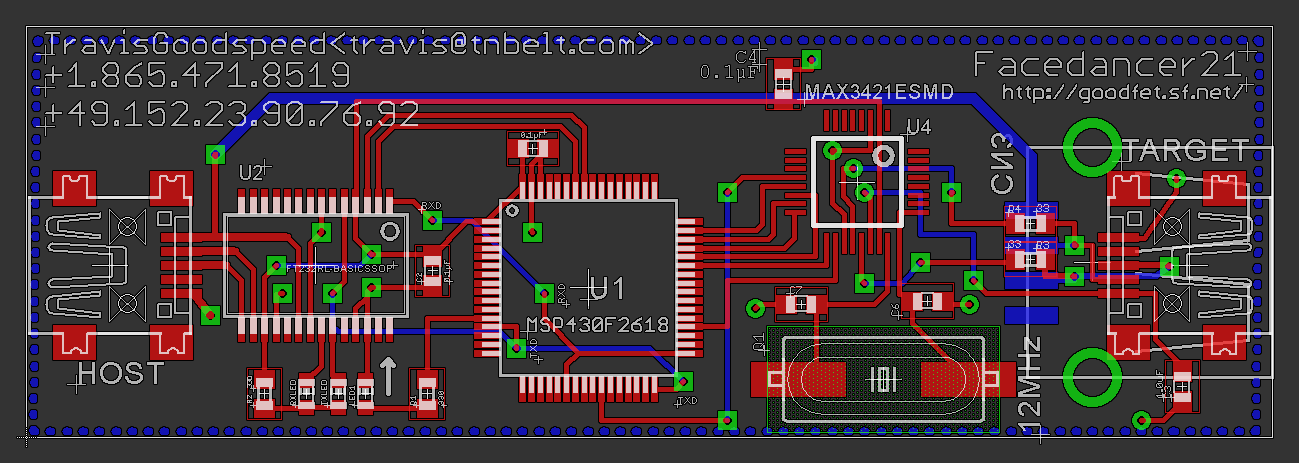
- Solder up the 3x 0.1uF caps to C1, C2, and C4 (Check the pcb layout below)

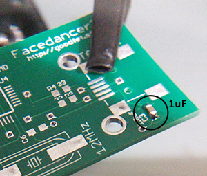
- Also solder the 1x 1uF capacitor to C3
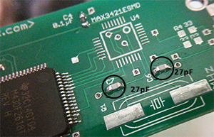
- The last capacitors to solder are the 2x 27pF for the crystal oscillator. C6 and C7
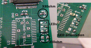
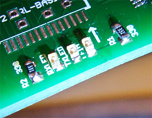
- Next is the row of 330ohm (2x) resistors and LEDs (3x). Tin each pad and move down the line. The little arrow on the bottom of the LED should be pointing in the same direction of the arrow on the silkscreen.
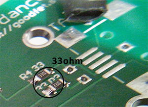
- Finish off the rest of the jelly bean parts by soldering the 2x 33ohm over by the
TARGETUSB footprint.
- Tack the MAX3421E chip down and drag solder each side just like the MSP430 in step 1.
- Solder up the 2x USB Mini connectors. Tack one of the ground legs down. Do not be afraid to reflow the joint and straighten out the connector. It will be extremely hard to adjust the connector once you solder another leg.
- Solder up the FT232RL. Tack and drag.
- Solder up the crystal. Nice and easy. Orientation does not matter.
- Optionally, solder up the USB Type A connector on the bottom side for host functionality. You will need to bend the pins in order to fit it down onto the board. You may also want to clip a few of the leads to get them away from other pads.
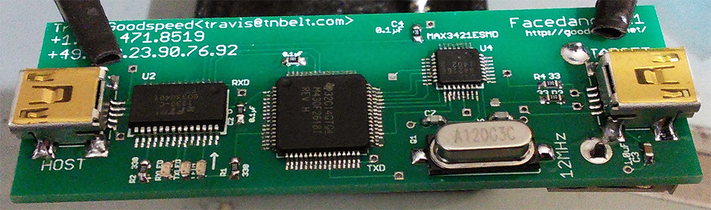
- Done:
Whats next?
Go flash your board. You can use my next guide in my Facedancer series: Facedancer21 Getting Started in Windows
Extra links:
- Emulating USB Devices with Python by Travis Goodspeed
- Writing a Thumbdrive from Scratch - Conference Talk: Travis Goodspeed
- SEC-T 2012 - Trashing USB layers using the Facedancer Board - Conference Talk: Travis Goodspeed
- The FaceDancer21: IMHO a simple example of our community at its best...
- Facedancer board lets your Python programs pretend to be USB hardware - Hackaday
- Solder Time! FaceDancer11 and GoodFET41 Assembly - Another assembly guide: By Brad Antoniewicz and Tushar Dalvi