Gitter Logo LED Sign Build Log
- led
- iot
- gitter
- beaglebone-black
I wanted more lighting around the apartment and was inspired by the lines that my blinds made on the wall on a sunny day which kinda match the Gitter logo (I work at Gitter/GitLab).
Boiled down, this project is some internet of things(IoT) connected LEDs.
Lines on the wall created by the blinds that inspired the sign,
Parts (bill of materials)
Electronics
- Beaglebone Black (rev. B), https://www.adafruit.com/product/1996
- USB battery bank, https://www.amazon.com/gp/product/B00L88VP3Y
- It's important to make sure that it can be charged and power another device at the same time because it will act as a universal power supply(UPS) for the Beaglebone Black so that it won't get corrupted if the power is cut.
- 400w, 1u power supply, https://www.amazon.com/gp/product/B014G2OUG2
- Any reliable slim power supply, <1.5" tall. I chose a 1u server form-factor power supply because it is about 1.5" tall.
- I went with a name-brand PC power supply because anything I have tried from eBay has eventually popped. Suggestions welcome!
- This power supply is quiet but not completely silent even without a load.
- RGBW LED strip (4 meters), https://www.adafruit.com/product/2439
- My strips were not individually addressable
- 4x IRLB8721P power MOSFETs (NPN transistors), https://www.adafruit.com/product/355
- Mini fans for cooling
- I used 12v fans and ran them at 7v by connecting them to a molex connector 5v(red) and 12v(yellow) pins to reduce the noise (
12 - 5 = 7, voltage is relative).
- I used 12v fans and ran them at 7v by connecting them to a molex connector 5v(red) and 12v(yellow) pins to reduce the noise (
- Female-to-female ethernet adapter
- Used so you can plug in an ethernet to the bottom of the sign and pass-through to the Beaglebone Black
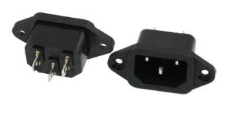
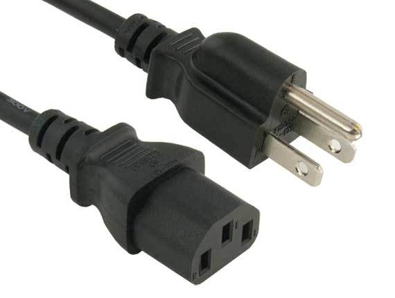
- Mountable female PC power connector (IEC320 C14)
- Momentary push button (power button for Beaglebone Black)
- On/off switch (for power supply)
- Protoboard
- Used for the power MOSFET circuit.
- Crimp connectors
- 4 or 5-pin JST connectors
- Used to easily connect LED strips to the power MOSFET circuit
- Various resistors
- Various wire
Physical/other
- Sheet of 1/2" MDF wood
- Aluminum LED U-channel (>3.328m), https://www.amazon.com/gp/product/B00VUAYFPK
- Used to better diffuse the light
- Search for "LED channel"
- Dust filter for air intake
- Search "dust filter" on eBay -> Buy it now -> "Price + Shipping: lowest first"
- Velcro
- Used to attach the LED strips to the U-channel
- There is a slot for the LED strip to slide into the U-channel but I wanted to leave the plastic sheath on the LED strips
- Spray Paint
- I used a Krylon white base and primer layer with Krylon Mamboo Pink on top (2-3 of each)
- Hanging hooks, https://www.amazon.com/gp/product/B000CSN35E/
- I used two of the 30lb hooks
Sign construction
The sign is made of 1/2" MDF wood and measures 1 meter x 1 meter and is 5cm deep. It's a simple 45deg corner box with an angled hanging bracket spanning across the entire width. The hanging bracket was angled just right for our hanging hooks to sit as flat and flash as possible against the wall.
The Gitter logo bars are split into two because I couldn't find LED channel that was wide-enough at this big of a proportion.
![]()
I ended up cutting these holes bigger with a keyhole/jab saw so I could feed the whole LED connector through the hole instead of soldering the connector after feeding the wires through. This makes maintenance easier because I can remove a whole strip and work on it on my desk instead of directly on the sign.
I used an old ladder to hang the sign while working on it.
Painting
To get the signature Gitter ruby/pink, #ed1965, I used a Krylon white base/primer layer with Krylon Mamboo Pink on top. I used 2-4 spray cans of each color to get full coverage on the sign.
Electronics
The brains
I used a BeagleBone Black(BBB, small Linux system like a Raspberry Pi) to control everything which allows me control the sign over the network and run any necessary smart server directly on the device. If you need some help setting up your Beaglebone Black and getting started, see my previous article. Currently, I just SSH into the BBB and run a Node.js script to adjust the LEDs.
The BeagleBone Black plugs into the USB battery bank which acts like an uninterruptible power supply (UPS). I run an ethernet cable from the BBB to a female-to-female ethernet adapter at the bottom of the sign. This makes it easy to connect/disconnect a separate ethernet cable at the bottom of the sign that goes off to the router/switch when the sign is hung up against a wall.
I also added an illuminated power button to the bottom of the sign for the BBB specifically. This is useful when you want to turn off the sign but you already put your computer to sleep and can't SSH into the sign. Or if you accidentally ran the shutdown Linux command and need to turn it back on. See the PWR_BUT pin for the button and SYS_5V pin for the LED.
UPS Battery bank powering off
I used a USB battery bank as a universal power supply(UPS) for the Beaglebone Black so that it wouldn't get corrupted if the power was cut.
The battery bank powers itself off if you don't draw enough current and you need to push the power button the battery bank to turn it back on again. Since I wouldn't have access to the power button when it is inside the sign against the wall, I ended up soldering a switch alongside to the existing momentary push button. This acts like the power button is always being pushed and keeps things rolling.
To reduce the power consumption and get rid of the needless light, I desoldered the LED backlight that is otherwise always on.
Other people on the web have pulsed some resistors/LEDs every 5 seconds to get the current threshold met but that seemed a lot more complicated.
- https://forum.pjrc.com/threads/28624-USB-Battery-Bank-Prevent-Shut-Down
- http://www.instructables.com/id/USB-External-Battery-Packs-on-Arduino-turns-OFF/
LEDs and wiring
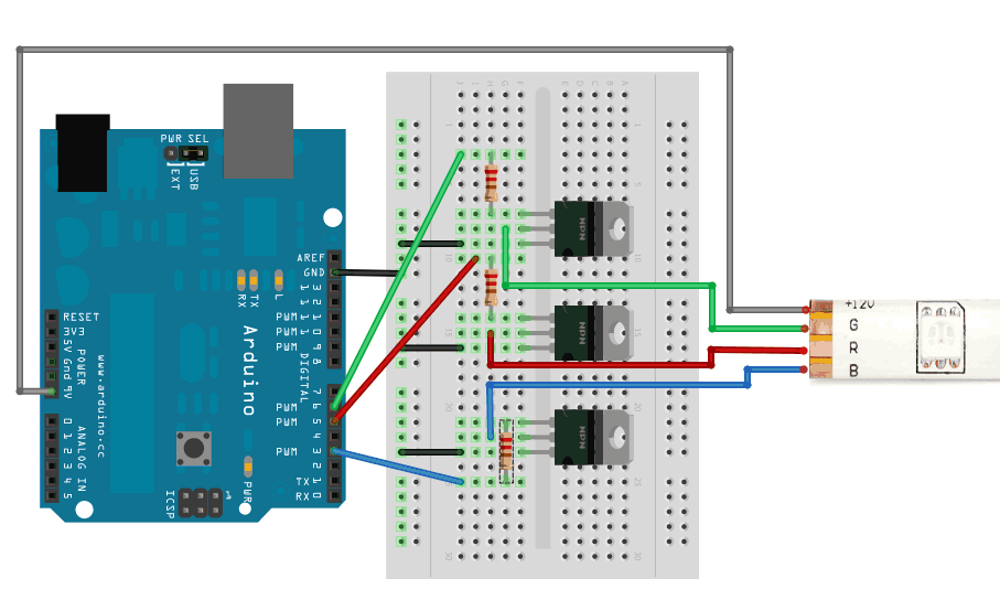
The LEDs are driven by IRLB8721P power MOSFETs (NPN transistors) and powered by a slim 400w server(1u) power supply. I wanted to control each LED strip and color independently but the Beaglebone Black doesn't have enough PWM pins so I ended up tieing all of the strips together and only have control of the color overall.
I used the same wiring setup for the MOSFETs and LEDs as this Adafruit guide for the analog LED strips shows. I also referenced this Electronics Stack Exchange answer about including a gate resistor.
In order to get the LED strips to lay flat, feed through the back of the sign, and not stick out from the aluminum channels, I had to solder the connector wires on the backside of the LED strip.
The LED strips are velcroed to the aluminum channel because I didn't want to remove the weatherproof sheath and it makes it easier to connect/disconnect from the sign. The adhesive backing of the velcro I used doesn't hold very well so I have to touch-up the sign whenever I notice one of the strips floating closer to the LED channel diffuser (bright spots).
I used some tape to keep wire bundles tidy and tied down to the sign.
Cutting LED strips at a non-segment
Most LED strips can only be trimmed at specific segments/intervals. In my case, it was every 3 LEDs. Because I needed to cut the LED strip in between a segment to get a custom length, I had to manually complete the circuit so the LEDs would turn on again. I couldn't find a schematic available online, so I desoldered all the components from a segment and peeled off the white solder mask to see what how the copper traces were connected (peeling worked much better than scraping it off).
Because I unknowingly cut some strips at different ends, I also had to wire them up differently. Here are the two variations and as you can see the first one is easier to wire up because everything connects to positive,
Accidentally connecting MOSFET heatsinks
Because I spaced the MOSFETs too close to each other, some of the MOSFET heatsink tabs were connected. This meant that any time either transistor gate for the blue or green LED channel were triggered, both drained. In a future iteration, I would space them apart which would also make adding heatsinks easier (see "Heating" section below).
![]()
This was easily fixed by bending them at different angles so they no longer touched,
Power supply (PSU)
I chose a slim 1u server form-factor power supply because it is about 1.5" tall. But it was still a little bit too tall so I used a chisel to carve out a little pocket in the MDF wood. I attached it via the 2 convenient screw holes on one side and some velcro on the bottom of the other side.
The power supply cable runs down to same female PC power connector (IEC320 C14) that is mounted at the bottom of the sign so I can easily connect a separate cable when the sign is hung up against a wall. I added a half of a paper cup around this wiring because I shocked myself while testing.
There is also a toggle switch to turn off the PSU. The switch is connected to pin 14(green) and 15(black ground) on the 24-pin power supply connector (Google "convert pc power supply into bench" for more info).
Heating and airflow
The MOSFETs get pretty hot so I added mini aluminum heatsinks to both sides of the metal tabs. The close spacing and different angles made this tricky.
Airflow wise, I channeled the power supply fan air directly outside and pointed some mini fans towards the MOSFETs which generate the most heat overall. I also added a fan to the hanging bracket so air could more quickly rise up and out of the sign.
Airflow diagram created with this project
![]()
For the in-take fans on the side of the sign, I used Gaffers tape to channel the air through a removable metal dust filter cut from a cheap PC fan filter.
I verified that things weren't getting too hot by using some helping hands to hold a thermocouple on the MOSFETs.
Code
Here is the basic Node.js script that runs on the Beaglebone Black and makes a nice warm glow.
var bone = require('bonescript');

var maxBrightness = 0.35;

bone.pinMode('P9_14', bone.OUTPUT);
bone.pinMode('P9_16', bone.OUTPUT);
bone.pinMode('P8_13', bone.OUTPUT);
bone.pinMode('P8_19', bone.OUTPUT);

function toggleBrightness(r, g, b, w) {
  bone.analogWrite('P9_14', r, 2000, printStatus);
  bone.analogWrite('P9_16', g, 2000, printStatus);
  bone.analogWrite('P8_13', b, 2000, printStatus);
  bone.analogWrite('P8_19', w, 2000, printStatus);
}

toggleBrightness(maxBrightness * 0.2, maxBrightness * 0.2, maxBrightness * 0.2, maxBrightness * 1);

function printStatus(x) {
  console.log(JSON.stringify(x));
}
For testing, rgb-cli.js, node rgb-cli.js --red=0.5 --green=0 --blue=1 --warm_white=1
var bone = require('bonescript');
var argv = require('yargs').argv;

var maxBrightness = 1;

bone.pinMode('P9_14', bone.OUTPUT);
bone.pinMode('P9_16', bone.OUTPUT);
bone.pinMode('P8_13', bone.OUTPUT);
bone.pinMode('P8_19', bone.OUTPUT);

function toggleBrightness(r, g, b, w) {
  bone.analogWrite('P9_14', r, 2000, printStatus);
  bone.analogWrite('P9_16', g, 2000, printStatus);
  bone.analogWrite('P8_13', b, 2000, printStatus);
  bone.analogWrite('P8_19', w, 2000, printStatus);
}

var red = parseFloat(argv.red || 0);
var green = parseFloat(argv.green || 0);
var blue = parseFloat(argv.blue || 0);
var warmWhite = parseFloat(argv.warm_white || 0);

console.log('RGBW', red, green, blue, warmWhite);

toggleBrightness(
  red * maxBrightness,
  green * maxBrightness,
  blue * maxBrightness,
  warmWhite * maxBrightness,
);

function printStatus(x) {
  console.log(JSON.stringify(x));
}
Here is a script to turn the lights off, off.js
var bone = require('bonescript');

var maxBrightness = 0;

bone.pinMode('P9_14', bone.OUTPUT);
bone.pinMode('P9_16', bone.OUTPUT);
bone.pinMode('P8_13', bone.OUTPUT);
bone.pinMode('P8_19', bone.OUTPUT);

function toggleBrightness(r, g, b, w) {
  bone.analogWrite('P9_14', r, 2000, printStatus);
  bone.analogWrite('P9_16', g, 2000, printStatus);
  bone.analogWrite('P8_13', b, 2000, printStatus);
  bone.analogWrite('P8_19', w, 2000, printStatus);
}

toggleBrightness(maxBrightness, maxBrightness, maxBrightness, maxBrightness);

function printStatus(x) {
  console.log(JSON.stringify(x));
}
Low frequency = High period bugs
When using a small frequency value
with analogWrite(pinString, dutyCycle, frequencyHz, callback),
the following error can be thrown, see https://gist.github.com/MadLittleMods/fbd0a55b3470bffa06a3759a6aa45c5e.
Future plans
In the future, it would be cool to hook this up to the Gitter API so that the color changes based on unreads(green)/mentions(orange).